
A picture is worth a thousand words. That’s why Unified Modeling Language (UML) diagramming was created: to forge a common visual language in the complex world of software development that would also be understandable for business users and anyone who wants to understand a system. Learn the essentials of UML diagrams along with their origins, uses, concepts, types and guidelines on how to draw them using our UML diagram tool.
Do you want to create your own UML diagram? Try Lucidchart. It's fast, easy, and totally free.
The Unified Modeling Language (UML) was created to forge a common, semantically and syntactically rich visual modeling language for the architecture, design, and implementation of complex software systems both structurally and behaviorally. UML has applications beyond software development, such as process flow in manufacturing.
It is analogous to the blueprints used in other fields, and consists of different types of diagrams. In the aggregate, UML diagrams describe the boundary, structure, and the behavior of the system and the objects within it.
UML is not a programming language but there are tools that can be used to generate code in various languages using UML diagrams. UML has a direct relation with object-oriented analysis and design.
There are many problem-solving paradigms or models in Computer Science, which is the study of algorithms and data. There are four problem-solving model categories: imperative, functional, declarative and object-oriented languages (OOP). In object-oriented languages, algorithms are expressed by defining ‘objects’ and having the objects interact with each other. Those objects are things to be manipulated and they exist in the real world. They can be buildings, widgets on a desktop, or human beings.
Object-oriented languages dominate the programming world because they model real-world objects. UML is a combination of several object-oriented notations: Object-Oriented Design, Object Modeling Technique, and Object-Oriented Software Engineering.
UML uses the strengths of these three approaches to present a more consistent methodology that's easier to use. UML represents best practices for building and documenting different aspects of software and business system modeling.
‘The Three Amigos’ of software engineering as they were known, had evolved other methodologies. They teamed up to provide clarity for programmers by creating new standards. The collaboration between Grady, Booch, and Rumbaugh made all three methods stronger and improved the final product.
The efforts of these thinkers resulted in the release of the UML 0.9 and 0.91 documents in 1996. It soon became clear that several organizations, including Microsoft, Oracle, and IBM saw UML as critical to their own business development. They, along with many other individuals and companies, established resources that could develop a full-fledged modeling language. The Three Amigos published The Unified Modeling Language User Guide in 1999, and an update which includes information about UML 2.0 in the 2005 Second Edition.
According to their website, The Object Management Group® (OMG®) is an international, open membership, not-for-profit technology standards consortium, founded in 1989. OMG standards are driven by vendors, end-users, academic institutions and government agencies. OMG Task Forces develop enterprise integration standards for a wide range of technologies and an even wider range of industries. OMG’s modeling standards, including the UML and Model Driven Architecture® (MDA®), enable powerful visual design, execution and maintenance of software and other processes.
OMG oversees the definition and maintenance of UML specifications. This oversight gives engineers and programmers the ability to use one language for many purposes during all phases of the software lifecycle for all system sizes.
The OMG defines the purpose of the UML as:
UML meets the following requirements:
The UML is popular among programmers, but isn’t generally used by database developers. One reason is simply that the UML creators did not focus on databases. Despite this, the UML is effective for high-level conceptual data modeling, and it can be used in different types of UML diagrams. You can find information about layering of an object-oriented class model onto a relational database in this article about Database Modeling in UML.
Do you want to create your own UML diagram? Try Lucidchart. It's fast, easy, and totally free.
UML is being continually refined. UML 2.0 extends UML specs to cover more aspects of development, including Agile. The goal was to restructure and refine UML so that usability, implementation, and adaptation are simplified. Here are some of the updates to UML diagrams:
Familiarize yourself with the UML vocabulary, with this list culled from the UML 2.4.1 document intended to help OMG non-members understand commonly used terms.
View the complete MOF document
System development focuses on three overall different system models:
These system models are visualized through two different types of diagrams: structural and behavioral.
The objects in UML are real world entities that exist around us. In software development, objects can be used to describe, or model, the system being created in terms that are relevant to the domain. Objects also allow the decomposition of complex systems into understandable components that allow one piece to be built at a time.
Here are some fundamental concepts of an object-oriented world:
UML uses elements and associates them in different ways to form diagrams that represent static, or structural aspects of a system, and behavioral diagrams, which capture the dynamic aspects of a system.
To illustrate how to create different types of UML diagrams, try one or all of these tutorials to guide you through the process of drawing both structural and behavioral diagrams.
Class diagrams represent the static structures of a system, including its classes, attributes, operations, and objects. A class diagram can display computational data or organizational data in the form of implementation classes and logical classes, respectively. There may be overlap between these two groups.
Component diagrams show how components are combined to form larger components or software systems. These diagrams are meant to model the dependencies of each component in the system. A component is something required to execute a stereotype function. A component stereotype may consist of executables, documents, database tables, files, or library files.

A deployment diagram models the physical deployment and structure of hardware components. Deployment diagrams demonstrate where and how the components of a system will operate in conjunction with each other.

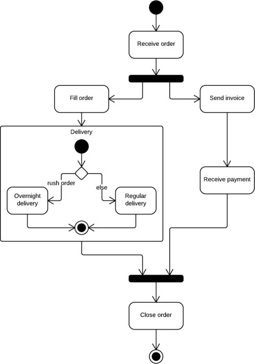
Activity diagrams show the procedural flow of control between class objects, along with organizational processes like business workflows. These diagram are made of specialized shapes, then connected with arrows. The notation set for activity diagrams is similar to those for state diagrams.
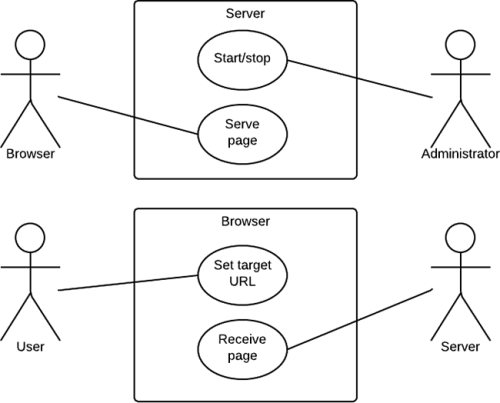
USE CASE DIAGRAM
A use case is a list of steps that define interaction between an actor (a human who interacts with the system or an external system) and the system itself. Use case diagrams depict the specifications of a use case and model the functional units of a system. These diagrams help development teams understand the requirements of their system, including the role of human interaction therein and the differences between various use cases. A use case diagram might display all use cases of the system, or just one group of use cases with similar functionality.
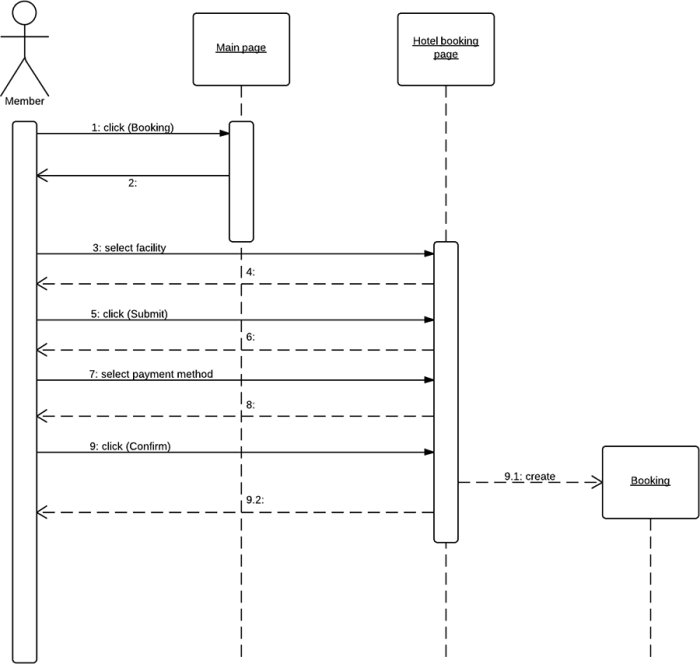
Sequence diagrams, also known as event diagrams or event scenarios, illustrate how processes interact with each other by showing calls between different objects in a sequence. These diagrams have two dimensions: vertical and horizontal. The vertical lines show the sequence of messages and calls in chronological order, and the horizontal elements show object instances where the messages are relayed.
You can start UML diagramming now with Lucidchart. We make it simple, efficient, and even fun.